Design in four steps: zoning, device schedule, calculations, approval package.
Reviewers check two calculations: voltage drop and battery standby capacity.
Submit all five documents together, with the same zone numbers in each.
Outside the United States, many specifiers still use NFPA 72, the U.S. National Fire Alarm and Signaling Code. They use it when a project needs a defined, checkable design process, not a rule of thumb.
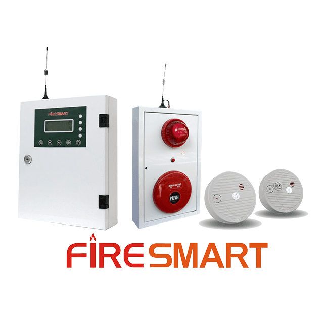
This walkthrough follows the sequence a designer works through on a real project: zoning, device selection, wiring calculations and the approval package. The worked example is FireSmart’s own conventional (FCP/FSP) panel line.
For detector spacing, see our separate detector spacing guide. This article covers the rest of the design process around it.
Before any device goes on a drawing, divide the building into zones. A zone is a group of devices that report to the panel as one identifiable area. Two things drive a good zoning plan:
A responder can tell roughly where in the building an alarm started, without checking every device.
Each zone’s wiring loop stays within the panel’s supervised-circuit limits.
On a FireSmart FCP or FSP panel, each channel supervises up to 32 detectors. So the channel count shapes the floor plan as much as the physical area does.
Building
Typical zoning
Panel
Small single-storey building
One or two zones
2–4 channel FCP
Multi-storey commercial building
One zone per floor, or per fire compartment
Larger FSP (10–40 channels)
The floor plan must mark these items, with the wiring routes drawn between them:
Every initiating device: detectors and manual call points.
Every notification device: sounders and strobes.
The panel location.
A regulator may not demand a specific drawing format. But the installer, the commissioning engineer and the person who maintains the system for the next ten years all need to read it without guessing.
Step 2 — The device schedule
A device schedule is a table. It turns a floor plan into a purchase order and an installation checklist at the same time. For each device it typically records:
Device type, manufacturer and model.
The zone or channel it belongs to.
Electrical characteristics: operating voltage and current draw.
The standard it is certified to.
On a FireSmart-based design, the table shows which device goes where:
Wherever the panel must report to a remote monitoring point or the local fire department, not only sound locally.
Step 3 — The calculations a reviewer will actually check
Two calculations come up in almost every NFPA 72-referenced design review.
Voltage drop
Every notification appliance circuit must deliver enough voltage to the farthest device on the loop. The device must have enough left over after the resistance of the wire itself. The standard working formula is:
Vd = 2 × L × I × R ⁄ 1000
Symbol
Meaning
Vd
Voltage drop, in volts.
L
One-way cable length in metres, from the panel to the farthest device on the circuit.
I
Total current draw of every device on that circuit, in amps.
R
Cable resistance in ohms per kilometre. It depends on the conductor material and cross-sectional area. A datasheet or wire-gauge table gives this figure.
The factor of 2 accounts for the round trip. Current flows out to the device and back to the panel.
Suppose the calculated drop leaves a device below its rated operating voltage. Fix it in one of these ways: a heavier-gauge cable, a shorter run or fewer devices on the circuit. Or split the circuit and add a repeater/expansion module. Do not hope the device still works at the margin.
Battery standby capacity
The backup battery must keep the system running through a defined standby period. Many jurisdictions’ adopted codes commonly set this at 24 hours. At the end of that period, the battery must still sound every notification appliance for several minutes of alarm.
To size the battery, follow these steps:
Add the panel’s own standby current draw and every connected device’s standby draw.
Multiply by the required standby hours.
Add the alarm-condition current draw for the required alarm duration.
The current-draw table in the panel’s datasheet is built to support this calculation.
Step 4 — Assembling the approval package
The local approval authority may differ. Reviewers almost always check for the same five items:
The zoned floor plan.
The device schedule.
The wiring/riser diagram.
The voltage-drop and battery calculations.
The manufacturer’s certification documentation for every device type used.
Submit all five together, cross-referenced by zone number. A reviewer can then approve the design in one pass, not send it back for missing calculations.
NOTE The most common reason a fire-alarm submission is delayed: the device schedule and the wiring diagram use different zone numbering.
The five-part package is the universal core. The approving authority and extra local layers differ by market. For example, see our notes on fire alarm compliance in the UAE, including the Hassantuk programme for villas.
Frequently Asked Questions
1️⃣ Is NFPA 72 a legal requirement outside the United States?
NFPA 72 is a U.S. code. Many countries and private specifiers outside the U.S. still use it as a design standard, even where it is not the legally adopted code. Check the locally adopted fire code for the project.
Use NFPA 72 as the quality reference where local code is silent on a detail.
2️⃣ Why does voltage drop matter if the panel already reports a fault for a wiring problem?
End-of-line supervision (available on FireSmart’s FCP/FSP panels) detects an open or short circuit. A circuit with excessive voltage drop is neither open nor shorted. It is intact but under-delivering. A sounder with too little voltage can be too quiet to meet the design’s coverage.
A fault report will not catch that. Only the calculation does.
3️⃣ Can heat detectors replace smoke detectors throughout a design to simplify it?
No. Heat detectors respond more slowly than smoke detectors. They need an actual temperature rise, not early combustion particles. Use them where smoke detection is impractical: dust, steam, cooking fumes and vehicle exhaust. Do not use them as a general substitute across a whole design.
4️⃣ Does a wireless FireSmart system need the same voltage-drop calculation?
No. A WCP-1 wireless addressable system removes the wiring runs for notification and initiating devices. Voltage drop along a field wiring loop does not apply. Battery standby calculations still apply, per device. Each wireless device runs on its own battery, not on a panel-supplied circuit.
5️⃣ Does FireSmart provide the design and calculation package for a project?
FireSmart supplies the device datasheets, current-draw figures and certification documentation you need for the calculations above. Contact FireSmart to discuss the device schedule and configuration for a specific project. Check FireSmart’s current Certifications & Compliance status before you specify devices for a project with a certification requirement.
30-SECOND SUMMARY NFPA 72-2025 makes cybersecurity a mandatory chapter and adds two new detector types. Above a 40-foot ceiling, detector spacing now needs a performance-based design. Trouble signals for a failed communication pathway are due within 200 seconds. NFPA 72 is the U.S. National Fire Alarm and Signaling Code. It is revised every three years….
30-SECOND SUMMARY Photoelectric detectors catch slow, smoldering fires earliest. Ionization detectors react fastest to fast, flaming fires. A tropical climate does not change the right technology. It raises the bar for sealing, drift compensation and cleaning. Use photoelectric for general areas and heat detectors for kitchens, boiler rooms and garages. Two detection technologies sit inside…
1. Understanding Fire Alarm System Components In the realm of fire safety, the fire alarm system stands as a pivotal element, ensuring the safety and protection of both lives and property. A fire alarm system is an amalgamation of various components, each playing a crucial role in detecting and alerting occupants in the event of…
30-SECOND SUMMARY A false alarm is an alarm with no real fire behind it. Most come from a few repeat causes: cooking fumes, dust or insects, construction dust, and detectors near HVAC vents. An addressable system helps you find the cause faster. A false alarm costs more than the evacuation itself. Each one erodes occupants’…
30-SECOND SUMMARY Check that the supplier owns its production line. Ask what is certified today and what is only in progress. Confirm sampling, quality control and lead time before you sign. An OEM or private-label order is not a one-off purchase. You trust a factory’s production line, quality process and paper trail for every unit…